Pinging from PC0 to VLAN 10 management IP address (192.168.10.100) will be successful as follows.

You can examine the IP addresses and port states of the interfaces with the show ip interface brief command in the switch. %LINEPROTO-5-UPDOWN: Line protocol on Interface Vlan30, changed state to up

%LINK-5-CHANGED: Interface Vlan30, changed state to up %LINEPROTO-5-UPDOWN: Line protocol on Interface Vlan20, changed state to up %LINK-5-CHANGED: Interface Vlan20, changed state to up %LINEPROTO-5-UPDOWN: Line protocol on Interface Vlan10, changed state to up

%LINK-5-CHANGED: Interface Vlan10, changed state to up SWITCH#conf tĮnter configuration commands, one per line. In CLI, execute the configure terminal command and then the interface command (name of the vlan) to configure the corresponding VLAN. To add management addresses for VLAN10, VLAN20, and VLAN30, addressing the network topology, follow these steps: In the Switch, this operation is performed in the settings of the VLAN you will assign IP.Ī management IP can be assigned for each VLAN created. The ip address command is used in the configuration mode of the port to assign an IP address to the interface of a router. NOTE: When you configure VLANs on the Layer 2 switch, if there is a Router in the environment, you need to configure the Inter-VLAN.Īssigning a Management IP Address to VLANsīy granting a management IP address to VLANs, you can control your devices from the local or remote network. The reason ping failed is that no routing has been made between the VLANs. When you ping PC4 from PC0 to VLAN30 member, ping will fail. When you ping between computers with other VLANs, you will see that the operation failed.Ī ping test from PC0 to PC2 which is a member of VLAN20 Since the network ports of PC0 and PC1 are connected to the VLAN10, you will see that there is a connection when you ping between these computers. SWITCH(config)# interface fastethernet 0/6Īfter adding the Switchport to the VLANs, check the interfaces you have created and made on the Switch with the show vlan command. SWITCH(config-if)# switchport access vlan 30 SWITCH(config)# interface fastethernet 0/5 To assign clients in the green zone to the VLAN20, perform the following commands in order. SWITCH(config)# interface fastethernet 0/4 SWITCH(config-if)# switchport access vlan 20 SWITCH(config)# interface fastethernet 0/3

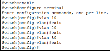
To assign clients in the blue zone to VLAN20, perform the following commands in order. SWITCH(config)# interface fastethernet 0/2 SWITCH(config-if)# switchport access vlan 10 SWITCH(config-if)# switchport mode access SWITCH(config)# interface fastethernet 0/1 To assign clients in the red zone to VLAN10, perform the following commands in order. Switch from privileged configuration mode on Cisco Switch to global configuration mode. Switch# conf tĪfter creating VLANs for departments, you need to make clients connected to the Switch interface to VLANs. Use the following commands to create a VLAN by topology. To change to Privileged mode, execute enable.Īfter making the basic settings, create 3 different VLAN groups according to the topology you have created on the Switch. First, add a Router, Switch, and six PCs to the Packet Tracer workspace to create a network topology as shown in the image below.Īfter configuring the Cisco Router’s interface and the TCP/IP settings of the computers, click Switch and click the CLI tab in the window that opens.


 0 kommentar(er)
